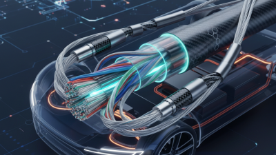
10 Tips to Choose the Right Automotive Cable?

Choosing the right automotive cable is no longer a routine purchasing task. Modern vehicles carry more data, power, heat, and vibration through tighter spaces. A cable that looks suitable on a workbench may fail after months near an engine, battery, or sharp bracket.

The International Energy Agency’s Global EV Outlook 2024 reports nearly 14 million electric car sales in 2023. It also records battery demand above 750 GWh for electric vehicles. These figures show why cable selection now requires closer attention to voltage, current, insulation, shielding, and thermal performance. In electric platforms, high-voltage cables must also support safe routing, reliable connections, and controlled electromagnetic interference. The IEA data reflects market growth, but it does not choose a cable for a specific vehicle.

That decision needs engineering judgment. ISO 19642 provides a relevant framework for automotive cables, while OEM specifications often add stricter requirements for abrasion, chemical exposure, flexibility, and flame behavior. During practical harness inspections, small details matter: a bend radius near a connector, oil around a seal, or a loose clip beside a vibrating panel. These details are easy to overlook. They should not be.

This guide presents ten practical tips for evaluating an automotive cable, from conductor construction to testing documentation. It considers both combustion-engine and electric-vehicle applications. Not every recommendation fits every platform. That is the uncomfortable part. A lower-cost cable may perform well in one location and fail in another. Reliable choices come from matching verified data with real operating conditions, then checking the result through testing and field feedback.

10 Tips to Choose the Right Automotive Cable?

Define the Cable’s Role in the Automotive Electrical System

Define the Cable’s Role in the Automotive Electrical System

Choosing the right automotive cable begins with defining its job. A cable may carry battery power, sensor signals, communication data, or a grounding path. These roles require different conductors, insulation, shielding, and connector designs. A high-voltage traction cable needs strong insulation and clear orange identification. A camera cable needs stable signal performance and controlled electromagnetic interference. They should never be treated as interchangeable.

The market is becoming more electrically demanding. The International Energy Agency’s Global EV Outlook 2024 reported nearly 14 million electric car sales in 2023, representing about 18% of global car sales. This growth increases the need for reliable high-voltage cables, charging circuits, and low-voltage control networks.

SAE J1128 provides guidance for several low-voltage automotive cable types, but a standard alone does not guarantee suitability. Current capacity, voltage drop, temperature, oil exposure, vibration, bend radius, and routing space must be checked together.

In workshop inspections, a cable can look oversized yet fail near a hot exhaust shield. That is easy to miss.

A smaller signal cable may pass electrical tests but create intermittent faults after repeated bending.

I would document the cable’s function, load profile, installation path, and failure risk before comparing prices. The specification sheet is useful, but not perfect. Real vehicle conditions still deserve a second review.
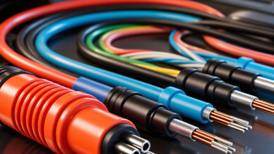
Match Voltage, Current, and Temperature Requirements

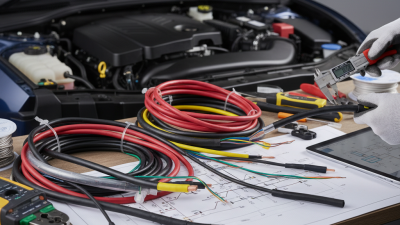
Choosing the right automotive cable starts with three numbers: voltage, current, and temperature. A cable may fit physically yet fail electrically. Check the vehicle circuit voltage, then confirm the cable’s continuous current rating. Short bursts can be acceptable, but repeated overload creates heat inside the insulation.

Tip: Add a safety margin. Do not select a cable that operates at its limit. In practical workshop testing, voltage drop becomes noticeable when the cable is too thin or excessively long. Measure the full cable route, including bends, terminals, and hidden connections. A longer path increases resistance. That detail is easy to miss.

Tip: Match the cable to its hottest location. Engine compartments can expose wiring to high temperatures, oil, vibration, and moisture. Choose insulation rated above the expected temperature, not merely the normal dashboard temperature. Keep in mind that bundled cables retain heat. This matters.

Tip: Recheck the installation, not just the specification sheet. Secure the cable away from sharp edges and moving parts. Use properly sized terminals and verify that crimps hold firmly. I have seen apparently correct wiring fail because one connection was loose. That was a useful reminder: cable selection and installation cannot be separated. When conditions are uncertain, record measured voltage drop and operating temperature before approving the final design.

Select the Correct Conductor Material and Cable Size

10 Tips to Choose the Right Automotive Cable?

Select the Correct Conductor Material and Cable Size

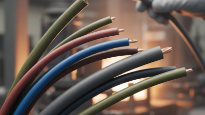
Conductor material directly affects resistance, heat, flexibility, and service life. Copper remains a practical choice because it carries current efficiently in compact engine compartments. Tinned copper adds corrosion resistance near batteries, coastal roads, and damp connectors. Aluminum is lighter, but it usually needs a larger cross-sectional area for the same current. It also requires careful terminal compatibility.

Cable size should match continuous current, peak load, cable length, and installation conditions. A starter circuit may tolerate brief high current, while lighting or cooling fans can operate for hours. Measure the complete circuit length, including the return path. Then check voltage drop, not only ampacity. A long cable can appear thick enough yet still deliver weak power at the load.

I once selected a cable by fuse rating alone. That was too simplistic. Bundled cables, hot exhaust areas, and tight routing increase operating temperature. Leave room for those conditions. Use the insulation temperature rating as a real design limit, not decoration. Flexible fine-strand construction helps cables survive vibration, but thin strands can be damaged by careless stripping. Inspect the conductor after cutting. Bright, clean copper is reassuring; darkened or loose strands deserve attention. In some installations, I would choose a slightly larger cable, although space and terminal fit still matter.

Check Insulation, Flexibility, and Environmental Resistance

Choosing the right automotive cable starts with insulation, not appearance. During workshop inspections, I look for cuts, swelling, exposed strands, and hardening near connectors. These small defects often appear before electrical failure. ISO 6722-1 classifies automotive cables by temperature resistance, including 105°C, 125°C, and 150°C categories. Select a rating above the cable’s measured operating temperature. A tight engine bay needs margin.

Flexibility matters when cables pass around brackets, hinges, or battery modules. Bend the cable gently by hand. It should move without cracking, whitening, or feeling unusually stiff. SAE J1128 provides widely used requirements for low-voltage road-vehicle cables, including insulation performance and conductor construction. However, a standard does not replace a real routing check. I once underestimated movement near a vibrating mounting point. The cable passed bench testing, but the bend radius was too small.

Environmental resistance deserves equal attention. Check exposure to oil, coolant, water, salt spray, heat, abrasion, and ultraviolet light. The U.S. Department of Energy’s 2023 Vehicle Technologies Market Report identifies 400-800 volt electrical systems as common in battery-electric vehicles. Higher voltage increases the need for dependable insulation and clean termination. Inspect the datasheet for temperature range, voltage rating, chemical resistance, and bend radius. Do not rely on “heavy duty” wording alone. It sounds reassuring, but it is not a test result. An overlooked detail can become the expensive one.

Verify Standards, Safety Ratings, and Installation Compatibility

Choosing the right automotive cable starts with evidence, not appearance. Verify the applicable standard, such as ISO 6722 or SAE J1128, and check its current revision. Ask for test reports, certification details, and batch traceability. A clear cable jacket is not proof of quality. I once trusted a neat label and overlooked an outdated temperature rating.

Check ten practical points: voltage, temperature, current capacity, conductor size, insulation type, flame behavior, abrasion resistance, chemical resistance, connector fit, and routing space. Select the cable by its real environment. An engine bay may expose it to heat, oil, vibration, and sharp edges. A larger conductor can reduce voltage drop, but it may not fit the terminal or bend safely.

Measure the route before ordering. Confirm the cable’s outside diameter, minimum bend radius, sealing method, and terminal compatibility. Inspect markings along the jacket, not only the packaging. Reliable suppliers should explain test methods and provide consistent documentation. Still, paperwork can miss installation mistakes. Leave enough slack, protect contact points, and secure the cable away from moving parts. Test continuity and voltage drop after installation. Do not skip the final inspection.

10 Tips to Choose the Right Automotive Cable? - Verify Standards, Safety Ratings, and Installation Compatibility
Tip Selection Dimension What to Verify Relevant Standard or Rating Why It Matters Installation Compatibility Check
1 Application and circuit function Identify whether the cable is for battery power, starting, charging, lighting, sensors, data communication, or a high-voltage traction circuit. Application-specific Different circuits require different insulation systems, conductor sizes, shielding methods, flexibility levels, and voltage ratings. Match the cable construction to the vehicle subsystem and the electrical architecture shown in the service documentation.
2 Automotive standard compliance Request a current datasheet and declaration of conformity showing the applicable test standard and cable designation. ISO 6722 for road-vehicle cables; ISO 19642 for automotive cables used in road vehicles; SAE J1128 for primary automotive wires in applicable markets. Recognized standards define construction, insulation performance, environmental resistance, and test methods. Confirm that the selected standard is accepted by the vehicle manufacturer, regulator, or project specification.
3 Voltage rating Check the cable's continuous operating voltage and compare it with the circuit's nominal and maximum voltage, including transient conditions. Low-voltage automotive circuits are commonly below 60 V DC; high-voltage vehicle systems require cable ratings specified for the complete HV architecture. A cable with insufficient voltage capability may suffer insulation breakdown, arcing, or electric-shock hazards. For high-voltage systems, use the specified orange or otherwise identified HV cable system only where required by the vehicle design and local rules.
4 Temperature rating Compare the cable's continuous temperature rating with the highest temperature near the engine, exhaust, inverter, battery, or other heat source. Typical automotive cable classes include approximately 85°C, 105°C, 125°C, 150°C, and higher, depending on the insulation system and standard. Operating above the rated temperature accelerates insulation aging and can reduce mechanical and dielectric performance. Allow for heat soak and nearby radiant heat; do not base the selection only on normal ambient temperature.
5 Current capacity and conductor size Determine the continuous load current, peak current, allowable voltage drop, conductor length, ambient temperature, and bundling conditions. Use the applicable wiring calculation method or vehicle engineering specification rather than relying on a universal ampacity table. Conductor size affects heating, voltage drop, efficiency, fuse coordination, and starting performance. Verify that the conductor fits the terminal, fuse, splice, and connector system; size the protection device for the complete circuit.
6 Insulation, fluid, and chemical resistance Check resistance to engine oil, fuel, coolant, brake fluid, cleaning agents, water, salt, and other fluids expected in the installation area. Look for documented fluid-resistance tests under the selected ISO, SAE, or vehicle-specific specification. Fluid exposure can cause swelling, softening, cracking, loss of adhesion, or reduced insulation resistance. Use additional conduit, sleeve, or sealing only when it is compatible with the cable and does not trap damaging fluids or heat.
7 Flexibility and vibration durability Assess conductor stranding, bend radius, flex-cycle performance, and resistance to vibration and repeated movement. Use the cable's stated minimum bend radius and documented flexing or vibration test results. Fine-stranded conductors and suitable insulation help reduce fatigue failures in engine, steering, door, seat, and suspension-related harnesses. Provide strain relief, avoid sharp bends, and secure the cable so that terminals do not carry repeated mechanical loads.
8 Abrasion, flame, and environmental protection Review abrasion resistance, flame behavior, water exposure, dust ingress, and resistance to stone impact or rubbing against vehicle structures. Verify the environmental tests required by the relevant cable specification and the vehicle harness design. Damaged insulation can create short circuits, corrosion, intermittent faults, and fire risks. Maintain clearance from moving or sharp components and use correctly sized grommets, conduit, clips, and protective sleeving.
9 EMI, shielding, and signal integrity Determine whether the circuit carries low-level sensor signals, high-speed data, audio, or high-current switching loads. For shielded or twisted constructions, verify the specified impedance, shielding coverage, twist characteristics, and termination method. Correct cable geometry and shielding can reduce electromagnetic interference and communication errors. Follow the vehicle's grounding and shield-termination strategy; avoid creating unintended ground loops or excessive unshielded pigtails.
10 Connector, terminal, routing, and service compatibility Match conductor cross-section, insulation outside diameter, terminal type, seal size, connector cavity, color coding, and routing space. Design-specific compatibility A cable can meet its electrical rating yet fail if it cannot be crimped, sealed, routed, repaired, or retained correctly. Use the specified crimp tooling and pull-test requirements; observe minimum bend radius, service loops, connector lock positions, and harness retention points.