How to Choose the Right Shielded Wire for Your Needs?

Choosing the right shielded wire begins with the signal, not the product label. A cable that works in a quiet laboratory may fail beside a motor, inverter, or radio transmitter. On real factory floors, interference often appears during startup, when current changes sharply and equipment vibrates.

This guide explains how to match shielded wire with voltage, frequency, flexibility, temperature, and installation conditions. Foil shielding can provide broad coverage and low weight, while braided shielding usually offers better mechanical strength and repeated flexing. Some designs combine both. The correct choice also depends on grounding methods, connector quality, cable length, and nearby electromagnetic noise. A technically strong cable can still underperform when its shield is terminated poorly.

Reliable selection requires more than comparing prices or shield percentages. Review the manufacturer’s datasheet, inspect construction details, and confirm tested performance under realistic conditions. Check the conductor size, insulation rating, bending radius, and compatibility with the equipment. Small sample tests can reveal problems before a full installation. Measure noise where possible.

No choice is perfect.

It is tempting to select the thickest or most heavily shielded option. That approach can add cost, stiffness, and installation difficulty without solving the actual problem. I have found that practical testing often challenges assumptions made from catalog specifications. This article provides a clear framework for choosing shielded wire with greater confidence, while recognizing that every application has its own electrical and mechanical demands.
How to Choose the Right Shielded Wire for Your Needs?

Understanding Shielded Wire and Its Purpose

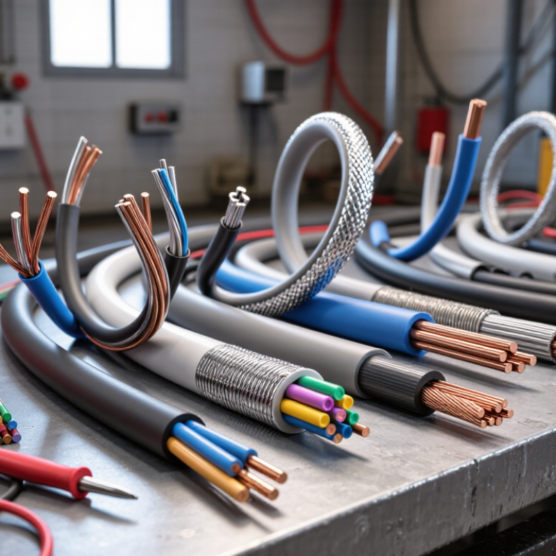
Shielded wire is designed to control unwanted electromagnetic interference. Its conductive layer surrounds the inner conductor and helps block electrical noise from nearby equipment. It also limits radiation from the signal itself. This matters around motors, relays, power converters, and communication devices.

The shield may use braided copper, foil, or both. Braid usually provides strong mechanical coverage and a practical grounding path. Foil can offer better high-frequency coverage, especially around small signal cables. A drain wire makes termination easier. However, shield performance depends on installation. A loose connection can defeat an excellent cable.

I once saw unstable sensor readings near a motor cabinet. The cable specification looked suitable, but its shield ended several centimeters from the connector. The exposed section acted like an antenna. Small details matter. Choose wire according to signal type, frequency, voltage, current, flexibility, and surrounding interference. For a low-level analog sensor, low capacitance may protect signal accuracy. For fast digital communication, impedance and high-frequency shielding deserve closer attention. In a moving machine, repeated bending may require a flexible braid and stronger insulation. Grounding at one end can reduce low-frequency ground loops, while high-frequency systems may need grounding at both ends. The correct method depends on the system design. I would verify it with measurements rather than assumptions. Check continuity, insulation, and noise levels under real operating conditions. The first choice is not always the best choice.
Defining Your Electrical and Environmental Requirements

How to Choose the Right Shielded Wire for Your Needs?

Defining Your Electrical and Environmental Requirements

Choosing shielded wire starts with the circuit, not the cable shelf. Record the operating voltage, current, frequency, and signal type. Low-level sensor signals often need better noise control than power circuits. Check impedance and capacitance requirements, especially for data or audio applications. A cable can look suitable and still distort a sensitive signal.

Then study the installation environment. Will the wire face heat, moisture, oil, sunlight, chemicals, or constant movement? Note the minimum bend radius and available space. In a moving machine, flexibility may matter more than maximum shielding. For fixed equipment, a foil shield can provide effective coverage. A braided shield often handles movement and physical stress better. Combination shields may be appropriate in severe interference zones.

Grounding also needs careful planning. A shield that is poorly terminated can become an antenna for unwanted noise. Confirm whether the design requires one-end or multi-point bonding. Follow the equipment instructions and applicable electrical standards. A qualified electrician or engineer should verify uncertain installations.

I once selected a cable with excellent shielding but excessive stiffness. It passed bench testing and failed during installation. That mistake changed my checklist. I now test a sample along the real cable path before ordering. Small details matter. Temperature ratings, connector compatibility, and jacket durability can decide long-term reliability. Requirements sometimes change after installation begins, so leave room for review.

Comparing Shielding Types and Coverage Levels

How to Choose the Right Shielded Wire for Your Needs?

Shielding coverage describes how much of the cable surface blocks electromagnetic interference. Foil shielding can provide nearly complete coverage. It uses a thin metal layer wrapped around the conductors. This design works well against high-frequency noise and keeps cable diameter small. However, foil can tear during repeated bending.

Braided shielding uses woven metal strands. Its coverage often ranges from 70% to 95%, depending on the braid density. It offers better mechanical strength and remains flexible in moving equipment. Lower coverage may allow more interference to pass through. A combination of foil and braid provides broader protection across different frequencies. It also costs more and may create a stiffer cable.

Coverage is not the whole answer. It is not that simple. I have seen a highly covered cable perform poorly because its shield termination was loose. A short, continuous connection to ground usually matters more than an impressive percentage. Check the operating frequency, bend movement, connector design, and installation length. For sensitive audio or measurement circuits, evaluate both electric-field and magnetic-field interference. Twisted conductors can reduce magnetic pickup before shielding is even considered.

Choose foil for compact, high-frequency protection. Choose braid when movement and durability matter. Select dual shielding when the environment contains mixed noise sources. Test the finished assembly if possible. Real installations often behave differently from laboratory specifications.

How to Choose the Right Shielded Wire for Your Needs? - Comparing Shielding Types and Coverage Levels

Shielding Type Typical Coverage Shield Construction Best Frequency Performance Flexibility Grounding Characteristics Typical Applications Key Advantages Limitations
Aluminum Foil 100% optical coverage Thin aluminum layer bonded to a polyester or similar carrier film, usually with a drain wire Very effective at high frequencies because the continuous foil provides a low-impedance surface Good for fixed installations; repeated flexing can damage the foil Usually requires a drain wire or conductive termination to establish a reliable ground connection Data cables, instrumentation, control wiring, and fixed cable assemblies Complete physical coverage, lightweight construction, and strong high-frequency protection Less resistant to repeated bending, twisting, and mechanical abrasion than a braided shield
Braided Copper or Tinned-Copper Shield Approximately 70–95% physical coverage Interwoven metal strands surrounding the insulated conductors Broadband performance with particularly good low-frequency and moderate-frequency noise reduction Good to very good, depending on braid density, strand size, and cable design Generally easy to terminate; the braid can provide a low-resistance path to ground Industrial control, audio, power electronics, robotics, and cables exposed to movement Strong mechanical protection, good durability, and effective low-frequency shielding Openings between strands allow some high-frequency energy to pass; heavier and often more expensive than foil
Spiral-Wound Shield Approximately 85–95% physical coverage Metal strands wrapped helically around the cable core Good low- and mid-frequency performance; high-frequency performance depends on overlap and construction Very good flexibility and suitable for repeated bending Usually straightforward to connect, but termination quality is important because the shield is not a continuous foil layer Microphone cables, flexible instrument leads, moving equipment, and compact cable assemblies Highly flexible, easy to process, and effective for many audio and control applications Coverage can vary with bending; performance may be less consistent at high frequencies than foil or combination shields
Foil and Braid Combination 100% foil coverage plus approximately 70–95% braid coverage Continuous foil layer combined with an outer braided metal shield Broadband protection across low, mid, and high frequencies Moderate; more flexible than foil alone in some designs, but generally less flexible than a spiral shield Provides a robust grounding path through the braid and a drain-wire connection to the foil Industrial automation, high-speed signaling, medical equipment, and electrically noisy environments Combines high-frequency foil performance with the mechanical strength and grounding capability of a braid Larger diameter, higher weight, increased stiffness, and higher material cost
Conductive Composite or Metallized Shield Varies by material and construction; commonly specified by the cable manufacturer Conductive polymer, metallized fabric, or other composite layer surrounding the conductors Application-dependent; may provide useful broadband protection when properly terminated Often very good, especially where low weight and repeated movement are important Grounding method varies; verify surface resistance, drain-wire requirements, and termination instructions Lightweight assemblies, flexible electronics, sensors, and specialized moving cables Low weight, design flexibility, and potential for excellent flex life Performance depends strongly on material quality, contact resistance, environmental stability, and termination method
Coverage values are typical industry ranges and may vary with braid angle, strand density, foil overlap, cable diameter, frequency, bending, and termination quality. For final selection, check the manufacturer’s published transfer impedance, shielding effectiveness, operating temperature, voltage rating, bend radius, and applicable safety standards.

Matching Wire Construction to Signal and Power Needs

How to Choose the Right Shielded Wire for Your Needs?

Matching wire construction to the signal or power requirement prevents many field problems. Start with the signal. Low-level sensor lines often need twisted conductors and a foil shield. Twisting reduces magnetic pickup. The foil provides broad coverage against electric-field interference. For repeated movement, a braided shield may last longer. It offers better flexibility and mechanical strength.

Power wiring requires a different decision. Check the conductor gauge, current rating, insulation temperature, and expected voltage drop. A thick conductor may carry motor current safely, but it can be unnecessarily rigid. For long runs, calculate resistance instead of trusting a basic size chart. Heat, bundled cables, and enclosed spaces can reduce the practical current capacity. The shield should not replace proper grounding or protective design.

Installation details matter as much as construction. Connect the drain wire according to the system’s grounding method. Poor termination can turn a well-shielded cable into an antenna. Keep noisy power conductors away from sensitive signal pairs where possible. I once selected a cable by shield coverage alone, and the result was disappointing. The signal passed, but its capacitance slowed a fast sensor response. That choice was not ideal. Measure impedance, capacitance, continuity, and voltage drop before approval. Leave room for uncertainty, especially when the cable will face vibration, moisture, or frequent bending.

How to Choose the Right Shielded Wire for Your Needs?

Matching wire construction to signal and power requirements

Low-Level Analog Signals

Use foil or foil-plus-braid shielding when maximum electric-field protection and low noise are important, such as sensor, audio, and instrumentation circuits.

High-Speed Digital Signals

Choose a controlled-impedance cable with consistent geometry, suitable pair twisting, and a foil or braid shield. Shield coverage alone does not guarantee signal integrity.

Power and Industrial Wiring

Prioritize conductor cross-section, insulation temperature rating, voltage rating, and thermal conditions. A braid or foil-plus-braid shield can help reduce electromagnetic emissions.

Shield coverage values are representative construction ranges. Actual performance depends on grounding, frequency, transfer impedance, cable geometry, installation, and termination quality.

Checking Compatibility, Safety, and Installation Requirements

Choosing shielded wire starts with the system, not the cable reel. Confirm conductor size, signal frequency, impedance, voltage rating, and connector type. A wire suited to low-level audio may fail in a fast data circuit. Check equipment manuals and terminal spacing before ordering. I once focused on shielding coverage and overlooked insulation temperature. That small mistake narrowed the installation options.

Compatibility also depends on the shield arrangement. Foil shields offer broad coverage, while braided shields often tolerate repeated movement better. Some cables combine both. Match the shield termination method to the equipment design. A drain wire can simplify grounding, but it cannot replace correct bonding. Keep signal and power conductors separated where possible. Verify current capacity, dielectric strength, and environmental ratings. Moisture, oil, vibration, and heat can change a safe choice.

Installation requirements deserve equal attention. Respect the stated bend radius, especially near plugs and cable glands. Avoid sharp stripping tools that nick the conductor or shield. Secure the cable without crushing its insulation. Ground the shield according to the circuit’s documented scheme; grounding both ends can create unwanted loops in some systems. Test continuity, insulation resistance, and signal performance before closing the enclosure. Do not trust appearance alone. A neat cable can still contain a hidden fault. Recheck the layout after installation, because real routing rarely matches the first drawing.